G Systems created an automated production test system to significantly reduce the test time and improve the test repeatability for a Distributed Antenna System product line. The use of LabVIEW allowed for automation of production quantities.
Utilize the rapid application development capability of LabVIEW to develop an automated test application to perform RF tests on the Fiber Optic Distributed Antenna subsystems. Utilize commercial offthe- shelf equipment including a GPIB controller and digital I/O board to control and acquire data from a custom test fixture, spectrum analyzer, and two RF signal generators.
The main components of the InCell system include the Central Unit (CU) and the Remote Unit (RU). A typical system consists of multiple RAUs tied into a CDU with fiber optic cable to provide an uplink and downlink path for RF signals.
One of the primary factors in the decision to develop an automated test capability for the product line was the length of time required to test the systems manually. The existing testing method involved using a signal generator and a spectrum analyzer to measure the RF characteristics of the system components manually. These manual tests could take up to a day to test a single system over various frequency bands.
This project required a configurable automated system that would perform the tests over a specified frequency range on both the RAU and CDU. The RF parameters to be tested included gain, frequency flatness, noise figure, and 3dB intercept. The system was also required to generate test reports and save the test results electronically.
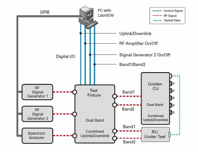
The test system diagram is illustrated in Figure 1. The National Instruments PCI-GPIB card controls the Agilent RF Signal Generators and Spectrum Analyzer, while the control lines to the test fixture are managed using the digital I/O signals from the National Instruments PCI-6503E card. The RAU was tested using a golden (known good unit) CDU and the CDU was tested using a golden RAU.

The configuration shown in Figure 1 is for testing an RAU. Testing a CDU is more involved because each CDU can handle multiple RAUs. Currently, the system instructs the operator to move the fiber optic cable from the golden RAU to each of the inputs on the CDU. In the future, this step might be automated with a fiber optic switching unit.
The user interface for the application is illustrated in Figure 2. The main panel allows the operator to enter the serial number and select the appropriate unit type and wireless standard. The program automatically determines the part number and mode from data stored in configuration files. The system handles two modes, single band and dual band. For dual band, all of the tests are repeated for each frequency band.
The operator can select individual tests to be performed through the user interface. Passing test results are displayed in green and any failed tests are flagged in red. This ability to perform single parameter tests is very useful in troubleshooting faulty units. Combined with the ability to use configuration files to set up new test parameters, the system is also ideally suited to allow evaluation tests to be performed in a timely manner in a research and development environment.
The application stores all data to a hard drive with individual test data being stored in a spreadsheet format. A specification sheet and an acceptance test report for the UUT are stored in HTML format. The HTML format was chosen to ensure that the acceptance test reports could be viewed by anyone on any system.
Based near Dallas, Texas, G Systems is an internationally recognized systems integrator specializing in the modernization of complex systems of all sizes. We are experienced in the design, integration, assembly, production, and maintenance of custom turnkey solutions that support our customers at all phases of their product’s maturity cycle.
NAICS Codes: 541330, 541715, 541511, 334515, 335999, 334519
CAGE Code: 3HPP5