G Systems delivered three test systems needed by NASA and Lockheed Martin engineers for performing structural tests on the Orion Multi-purpose crew vehicle in a six moth timeframe.
G Systems used concurrent development and leveraged off-the-shelf National Instruments (NI) hardware and software tools to deliver all three systems within the short delivery time frame. LabVIEW™ software is used extensively in all three systems as well as an array of PXI, SCXI, and cRIO™ hardware.
The first structural test for the Orion Ground Test Article (GTA) was successfully conducted in August of 2010. This proof pressure test at 1.05 atmospheres required three distributed systems that work together:
G Systems developed each system using National Instruments hardware and software components which enabled short development cycles for advanced functionality. An overview of the relationships between the various system elements is shown below.

Figure 2: System Architecture Overview
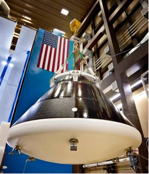
Figure 3: Orion Crew Vehicle during Proof Pressure Test (Photo Courtesy of Lockheed Martin)
The P&V system is responsible for precisely controlling the interior pressure of the crew vehicle during testing. The P&V system is a portable cart with high-pressure gas bottles that provide the gas needed for the pressurization process.
Figure 4: Pressurization and Vent System
This system has a control unit built around NI’s cRIO industrial computer and controls pressure while simultaneously monitoring for critical faults or alarms. The cRIO with LabVIEW RealTime (RT) was selected to provide reliable control of this critical process. A “brick PC” with touch screen provides a LabVIEW graphical user interface (GUI) in a removable pendant form factor so that the operator can control the pressurization process from a safe location.
The DAS is responsible for collection of parametric data – primarily for strain measurement. The heart of the DAS system is a PXI LabVIEW RT system that collects over 1,800 channels of synchronized data. In addition, the DAS has capability to calculate several thousand synchronized, user-defined, virtual channels while also monitoring alarm and limit levels that may trigger a test shutdown. A quad-core PXI RT controller performs all of these activities in parallel and has been optimized to execute specific loops on each processor in order to maintain deterministic performance.
DAS data is logged to TDMS files which are later transferred to the DDS file server. While a test is in progress, all data is streamed across a network to clients for real-time viewing. Figure 5 illustrates the DAS equipment rack, an interior view of one of seven SCXI chassis, and the configuration GUI provided for system setup and control.
Figure 5: Data Acquisition System
A DAS control computer is provided for programmatically changing system configuration via network connection and for defining calculated channels, alarms, and limits.
The DAS also includes ruggedized cabling and patch panels using Mil-spec circular connectors for ensuring reliable signal connections.
Maintaining calibration on high channel count systems is a challenge in and of itself. For this purpose, G Systems developed a verification system that enables an operator to connect a cable to each of the 42 front panel connectors and automatically run a calibration verification routine on each channel on that connector. The calibration system uses a source measurement unit and a switching DMM to check the strain module excitation source and sense lines and verify that they fall within acceptable levels before each test.
Collecting, synchronizing, and presenting several thousand channels of data in real-time and post-playback can be a significant challenge. The DDS provides this capability. Not only does the DDS present data from the P&V and DAS but also from 32 IP cameras and eight microphones that are situated near the test article to observe the test in progress. The network diagram in Figure 6 illustrates the distributed nature of the entire system and sources of data that are aggregated by the DDS.
Figure 6: Network Infrastructure
Six or more test observers use LabVIEW-based GUIs to view tests in progress or retrieve past test data. At any time, users can view real-time data for a test in progress, buffered real-time data, or logged data from previous tests. DDS includes two dedicated video servers for logging and streaming video channels. DDS also includes encoders to convert analog audio to IP-based streams that can be used in real-time or streamed back in MP3 format. Test configuration and parametric data stored in TDMS files are stored on a dedicated server that also serves as the test network domain controller.
Test observers are given the capability to define their own multi-screen GUIs with selectable size and position of tables, graphs, and video windows. They can save these configurations and recall them later for recreating the same data channel collections and views. The LabVIEW GUI operates on any Windows laptop as well as dedicated client machines that display the GUI on large, wall-mounted, multi-media displays for group observation or demonstration.
Figure 7 illustrates the DDS server rack and configurable GUI.
Figure 7: Data Distribution System
These three systems illustrate the power of using National Instruments hardware and software both in their advanced capabilities and in the rapid development timeframe that G Systems achieved. Each of the three illustrates the benefits of specific National Instruments products:
Based near Dallas, Texas, G Systems is an internationally recognized systems integrator specializing in the modernization of complex systems of all sizes. We are experienced in the design, integration, assembly, production, and maintenance of custom turnkey solutions that support our customers at all phases of their product’s maturity cycle.
NAICS Codes: 541330, 541715, 541511, 334515, 335999, 334519
CAGE Code: 3HPP5