G Systems delivered a turnkey solution that reduces testing time, increases accuracy, and provides a full automation of the system.
G Systems delivered a turnkey solution that reduces testing time, increases accuracy, and provides a full automation of the system.
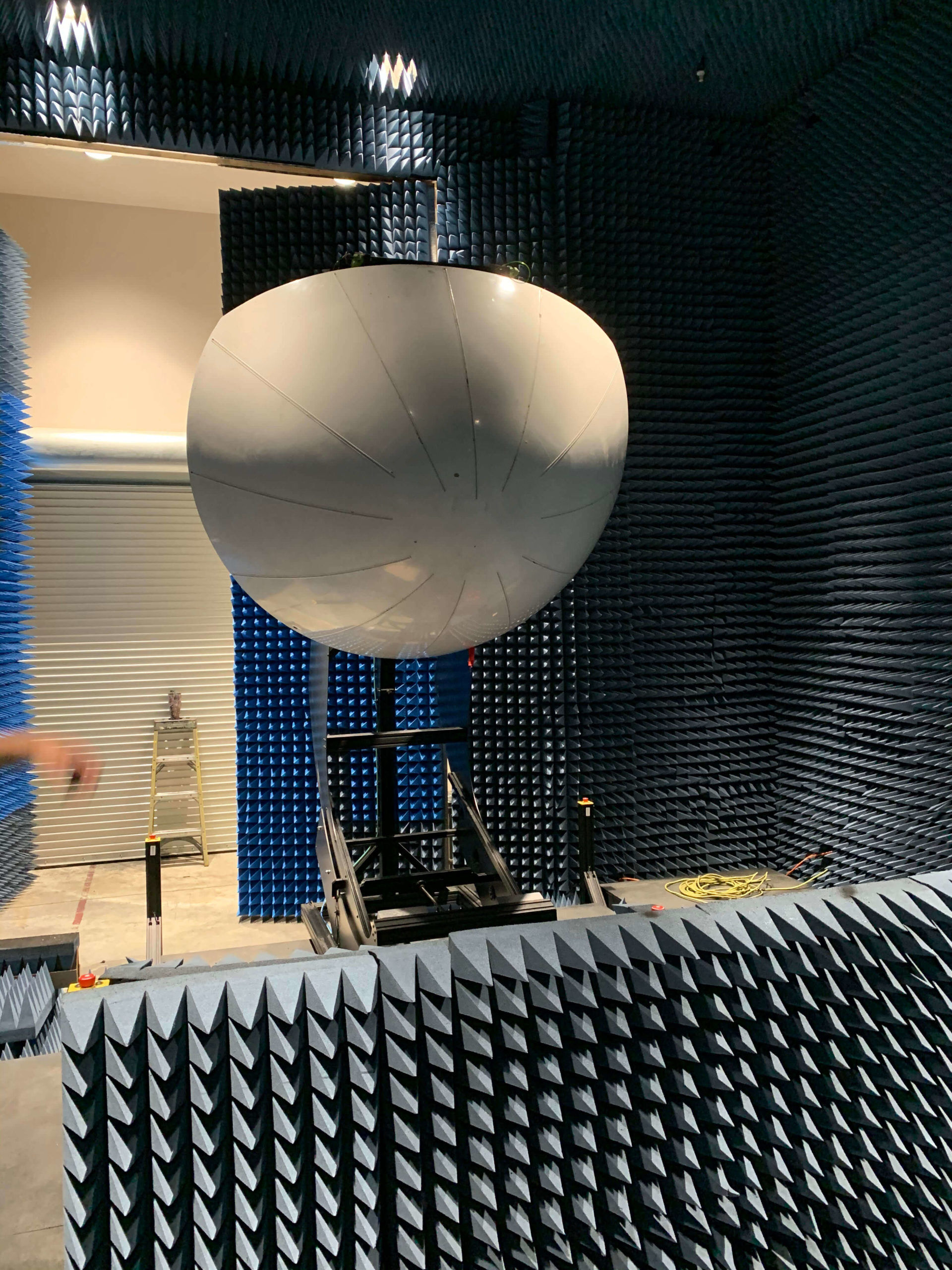
At the very nose of an aircraft is a composite aerodynamic cone called a radome. Its function is to protect critical weather radar equipment from the elements while allowing for proper RF transmissivity. From time to time these radomes get damaged and require repair and airworthiness approval and certification to RTCA DO-213a standards by an FAA approved repair station.
In a perfect world, radomes would be as indestructible as they are essential. In reality however, because radomes are made of lightweight composite material, they are easily and frequently damaged. This damage is often thought of as primarily caused by blunt-force strikes from birds, hail or “hanger rash” from improper storage or maintenance. Although true, the lesser known reality is that most damage caused to radomes is directly attributed to static electricity. In low humidity conditions the static electricity on its surface can build up resulting in rapid discharge causing chipping of the paint and small pinholes permanently burned in the surface.
The repair process on these radomes necessitates an automated testing process that is precise and quick as to reduce extended Aircraft On Ground (AOG) situations.
That’s where G Systems comes in!
G Systems developed and now produces a turnkey solution that consists of:
The test system is capable of conducting transmissivity testing, as well as side lobe testing. The standard system operates in C band and X band frequency ranges and conducts measurements in accordance with RTCA DO-213a requirements for aircraft weather radar.
Once the system has been installed at a customer’s facility, operators without any RF expertise can measure radomes using the G Systems built-in measurement software wizard.
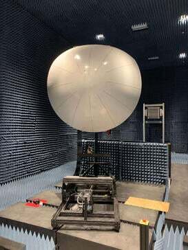
The tester’s operating day begins with a calibration procedure, conducted without a radome attached. During normal use, operators will be guided through a process of mounting the radome to the calibrated test system’s positioner. Measurements and calibration are conducted across the radome’s entire viewing window as described in the RTCA DO-213a standard. This includes measuring from -80 degrees to +80 degrees around the radome’s azimuthal axis and from -20 degrees to +20 degrees on the elevation axis.
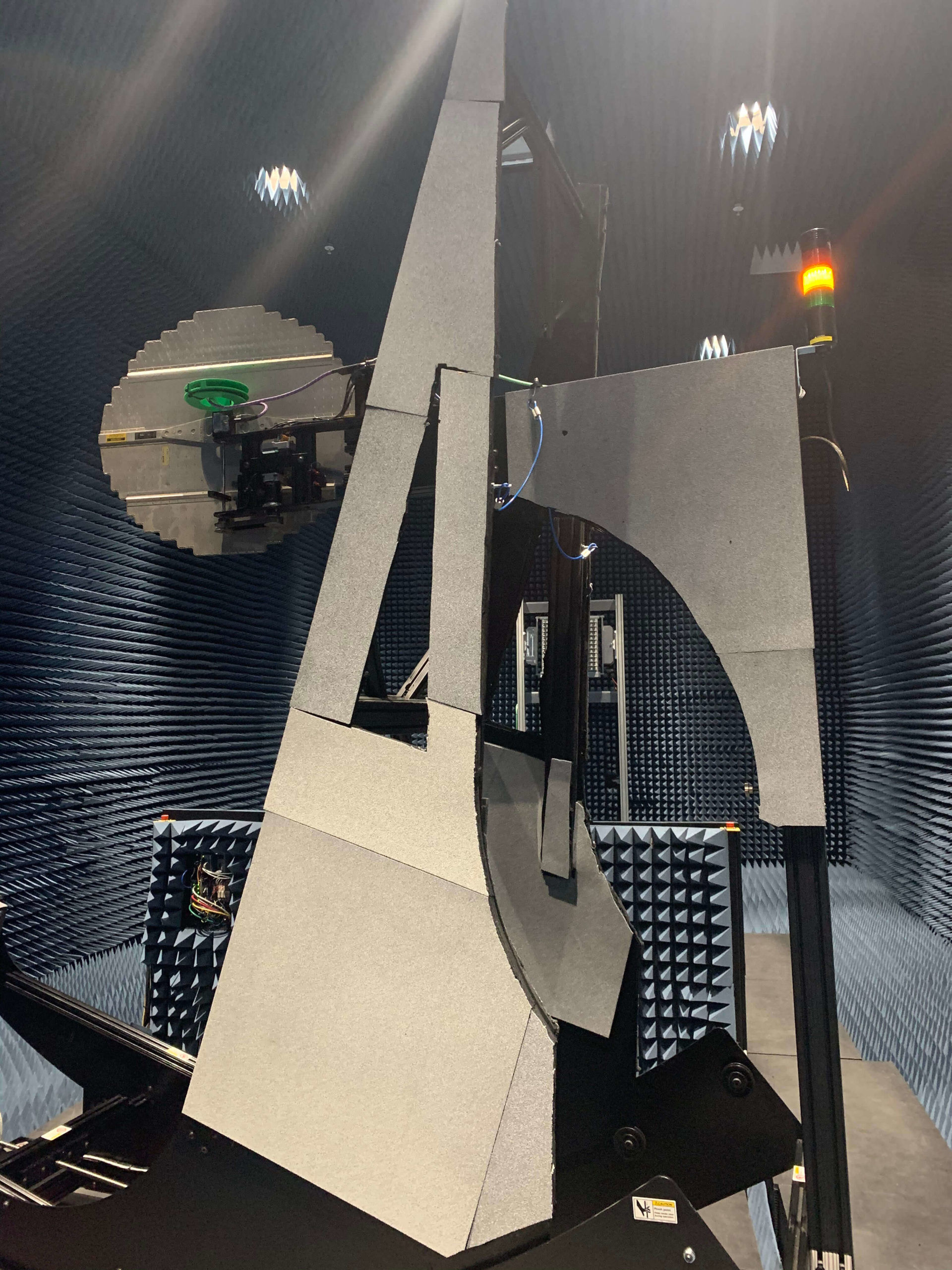
The Turnkey Radome Test System has three degrees of motion, enabling the test software to change the radome’s orientation in respect to the range antenna along two axes, representing the azimuth and elevation. A third degree of motion allows the test software to reposition the test antenna. Another motion feature is the automatic side lobe positioner, which enables the user to test all sidelobe requirements and evaluate for increase in Side Lobe Levels (SLLs.) A fourth motion axis controls range antenna translation to move between ¼ wave positions.
G Systems’ Radome Transmissivity Test Software is the final component to the fully automated system. It includes several operating modes, the primary of which is a wizard-style step-by-step process. The wizard interface walks an operator through the automatic calibration and prompts for loading and testing of a radome. The software also includes a manual operation mode, allowing the user to test a radome by moving it to a particular set of angles and taking a singular measurement for analysis purposes. A report is produced upon completion, which includes the radome’s letter grade and a map of all measured points.

“This system highlights G Systems’ full turnkey capabilities, combining mechanical, electrical, software, and RF engineering. Our diverse range of disciplines enables us to deliver a fully automated system to our clients.”
– JAMES DUVALL, Senior Project Engineer

The benefits of G Systems’ solution can be pinpointed by looking at speed, accuracy and automation. The ease of use of the positioning fixture, enables quick loading and unloading while the software and precision Vector Network Analyzer ensure minimal dwell time at each measurement point.
G Systems’ custom range antenna designs allow the test system to be installed in a much smaller anechoic chamber while meeting RTCA DO-213a requirements for far field measurements (phase flatness and amplitude flatness). The custom antenna allows for far field measurements which are much faster than other compact range technology which relies on near-field measurements.
G Systems’ solution does not require a reflector to artificially increase the electrical length of the room. This is highly beneficial because such a room design is much more expensive and requires a great deal more calibration and alignment.
The best way to begin is by having a conversation with a member of the G Systems teams about your test challenges and the options for helping you solve them.
Based near Dallas, Texas, G Systems is an internationally recognized systems integrator specializing in the modernization of complex systems of all sizes. We are experienced in the design, integration, assembly, production, and maintenance of custom turnkey solutions that support our customers at all phases of their product’s maturity cycle.
NAICS Codes: 541330, 541715, 541511, 334515, 335999, 334519
CAGE Code: 3HPP5